Logic Gates
Logic gates are the basis of digital electronics. A logic gate is an idealized or physical device which performs a logical operation on one or more logic inputs and produces a single logic output. A logic gate is an electronic circuit which makes logical decisions. An ideal logic gate is the one that has zero rise time and unlimited fan-out. Diodes or transistors acting as electronic switches,implement logic gates. Electromagnetic relays, fluidic logic, pneumatic logic, optics, molecules and mechanical elements can also be used to implement logic gates. Logic circuits include multiplexers, registers, arithmetic logic units and computer memory. Microprocessors contain more than 100 million logic gates. Gates are made from field-effect transistors. Compound logic gates AND-OR-Invert (AOI) and OR-AND-Invert (OAI) are constructed from MOSFETs (metal–oxide–semiconductor field-effect transistors) and hence they are simpler and efficient. Transistors or relays, vacuum tubes are used to create functionally complete logic systems. The output of one gate can only drive a finite number of inputs to other gates, a number called the 'fanout limit'. Elementary logic gates have commonly two sets of symbols used for them. They are defined in ANSI/IEEE Std 91-1984 and its supplement ANSI/IEEE Std 91a-1991. The NOT gate is commonly called an inverter. The circle on the symbol is called a bubble,
and is used in logic diagrams to indicate a logic negation between the
external logic state and the internal logic state (1 to 0 or vice
versa). In the 1980s, schematics were the predominant method to design both circuit boards and custom ICs known as gate arrays.
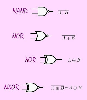
Consider different kinds of gates:
- AND Gate
- OR Gate
- NOT Gate
- BUF Gate
- NAND Gate
- NOR Gate
- XOR Gate
- XNOR Gate
INPUT
|
OUTPUT
|
|
A
|
B
|
A
AND B
|
0
|
0
|
0
|
0
|
1
|
0
|
1
|
0
|
0
|
1
|
1
|
1
|
Truth Table for OR gate
INPUT
|
OUTPUT
|
|
A
|
B
|
A
OR B
|
0
|
0
|
0
|
0
|
1
|
1
|
1
|
0
|
1
|
1
|
1
|
1
|
Truth Table for NOT gate
INPUT
|
OUTPUT
|
A
|
NOT
A
|
0
|
1
|
1
|
0
|
Truth Table for NAND gate
INPUT
|
OUTPUT
|
|
A
|
B
|
A
NAND B
|
0
|
0
|
1
|
0
|
1
|
1
|
1
|
0
|
1
|
1
|
1
|
0
|
Truth Table for NOR gate
INPUT
|
OUTPUT
|
|
A
|
B
|
A
NOR B
|
0
|
0
|
1
|
0
|
1
|
0
|
1
|
0
|
0
|
1
|
1
|
0
|
Truth Table for XOR gate
INPUT
|
OUTPUT
|
|
A
|
B
|
A
XOR B
|
0
|
0
|
0
|
0
|
1
|
1
|
1
|
0
|
1
|
1
|
1
|
0
|
Truth Table for NXOR gate
INPUT
|
OUTPUT
|
|
A
|
B
|
A
XNOR B
|
0
|
0
|
1
|
0
|
1
|
0
|
1
|
0
|
0
|
1
|
1
|
1
|
 |
| Logic Gates AND, OR, NOT |
 |
| Logic Gates NAND, NOR, XOR, XNOR |
Comments
Post a Comment